Introduction of Control Unit and its Full Design by CodeTextPro
Definition of Control Unit:
The CU of CPU is responsible for controlling system operations by routing the selected data items to the selected processing hardware of ALU at the right time and activate associated processing hardware Units by generating a set of signals that are synchronized with a master clock.
Responsibility of Control Unit:
A control unit performs the following responsibilities:
- Instruction interpretation
- Instruction sequencing
Instruction Interpretation (Instruction Decode Phase): During the interpretation phase, the control unit performs the following actions:
- Reads instructions from the memory
- Resolves the instruction type and addressing mode
- Gets the necessary operands and routes them to the appropriate functional units of the execution unit.
- Generation of required signal to the different Units of ALU to perform the desired operation.
 |
| General-purpose microprogrammed control unit |
Instruction sequencing (Instruction Fetch Phase): During the sequencing phase, the control unit finds the address of the next instruction to be executed.
Types of Control Unit:
There are two types of control unit -
1) Hardwired Control unit
2) Microprogrammed Control unit
Hardwired Control unit: When the control signals are generated using conventional sequential logic design techniques, the control unit is said to be hardwired. The sequential logic circuit generates specific sequences of control signals in response to externally supplied instructions. Logic gates, flip flops, decoders and other digital circuits are used to implement hardwired control
organization.
Disadvantage:
If the design has to be changed or modified, a hardwired control unit
requires changes in the wiring among the various components.
Microprogrammed Control unit: It is a control unit whose binary control variables are stored in memory (control memory). The control memory is programmed to initiate the required sequence of microoperations.
Advantage:
Any required change can be done by updating the microprogram in
control memory
Some Basic Definitions
Control Variables: It is represented by binary 0 and 1.
Control Word: The groups of control variables (string of 1’s and 0’s.) which are activated at a time to perform some operations are called control word.
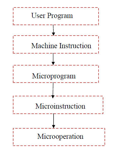
Microinstruction (Control Word in Control Memory): The microinstruction specifies one or more microoperations.
Microprogram : A sequence of microinstruction.
The sequence can be represented as follows:
Comparison Between Two Methods:
Hardwired Control unit:
1. Less expensive
2. Logic is generated by conventional sequential circuit.
3. No separate memory is needed.
4. Once the control unit of a hardwired computer is designed and
built, it is virtually impossible to alter its architecture and instruction set.
5. It is faster.
6. Zilog’s 16-bit microprocessor Z8000 have hardwired control unit.
Microprogrammed Control unit:
1. More expensive
2. Logic is generating through microprogramming.
3. Separate memory (control memory) is needed to store microprogram.
4. In the case of a microprogrammed computer, simply altering the microprogram stored in its control memory can change the computer’s instruction set.
5. It is comparatively slower.
6. IBM 370, PDP-II and Intel 80x 86 families have microprogrammed control units.
Microprogrammed Control Unit
It is a control unit whose binary control variables are stored in memory (control memory). The control memory is programmed to initiate the required sequence of microoperations.
Components of Microprogrammed Control Unit
The components of Microprogrammed Control Unit are-----
- Microprogram Counter (MPC)
- Control Memory
- Control Memory Buffer Register (CMBR)
- Multiplexer (MUX)
- Decoder
Microprogram Counter (MPC): The task of MPC is same as the PC (program counter) used in the CPU. The address of the next microinstruction to be executed is held by the MPC. Using this address we fetch the control word from control memory.
Control Memory: The control memory is usually a ROM, which holds a fixed microprogram that cannot be altered by the occasional user. All control information stored in control memory is permanent in nature.
Control Memory Buffer Register (CMBR): The function of CMBR is same as the MBR (memory buffer register) of the main memory. It is basically a latch and acts as a buffer for the microinstructions retrieved from the CM. It holds the microinstruction to be executed (current microinstruction).
MUX: it specifies external condition to be tested during execution of
microprogram.
Microinstruction Format:
Typically, each microinstruction has three fields as:
- Condition Select
- Branch Address
- Control Function
The condition select field selects the external condition to be tested. The output of the MUX will be 1 if the selected condition is true. The MPC will be loaded with the address specified in the branch address field of the microinstruction, because the output of the MUX is connected to the load input of the microprogram counter (MPC). However, the MPC will point to the next microinstruction to be executed, if the selected external condition is false. Thus, this arrangement allows conditional branching. The control function field of the microinstruction may hold the control information in an encoded form which thus may require decoders.
Working Principal:
1. Initially, MPC is loaded from an external source to point to the starting address of the microprogram to be executed.
2. From then on, the MPC is incremented after each microinstruction fetch to point the address of the next microinstruction.
3. We fetch the microinstruction (control word) from control memory based on address specified by MPC.
4. The instruction fetched from control memory is transferred to the CMBR. If the control functions in the instruction is in encoded format then decoder is used to decode the control function.
In case of branching:
1. The MPC will be loaded with the contents of the branch address field of the microinstruction that is held in the CMBR.
2. Branch will be executed or not is decided from the output of MUX. Based on the contents of the condition select field of the microinstruction, MUX selects one of the external conditions. If the selected condition is true then the output of the MUX will be 1 and MPC will be loaded with the address specified in the branch address field of the microinstruction. However, the MPC will point to the next microinstruction to be executed, if the selected external condition is false.
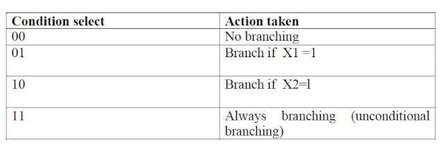
3. Suppose two external conditions X1. X2 are to be tested; then the condition select and actions taken are summarized next:
4. The multiplexer has four inputs V0, V1, V2. V3 where Vi is routed to the multiplexer’s output when the condition select field has decimal equivalent i. Hence we require V0 = 0, V1 = X1 V2 = X2 V3 =1 to control the loading of microinstruction branch addresses into MPC.


1 Comments
2A5D520F8E
ReplyDeleteinstagram takipçi hizmeti
boucle swivel accent chair